Buildup: Type I “Cricket” Phaser
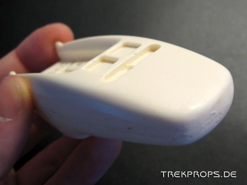
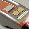 The Type I phaser from TNG, a prop barely 9 centimetres long. To do a replica of this can’t be much trouble, right? Wrong! The smaller the object is, the finer are the details and the more time has to be spent to make the prop look good. I will describe here what I did to build this “cricket” phaser up. When I got the kit from a member of the ASAP board , it was in a pretty raw shape, which is not uncommon for resin castings however. This meant that the surface had to be smoothed out (especially on the sides), pinholes had to be filled and even certain areas of the body had to be reshaped:
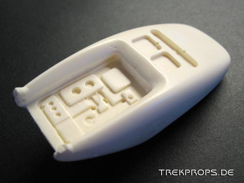
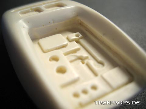
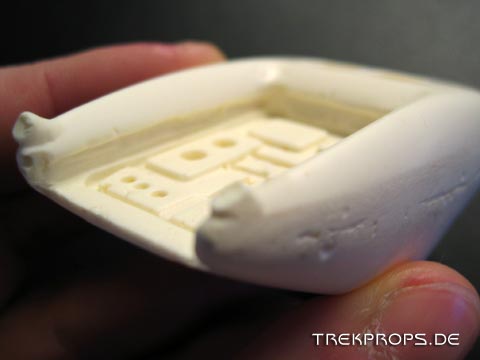
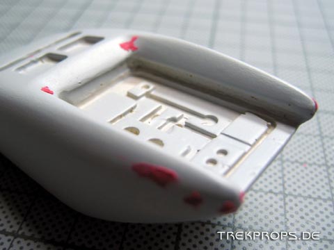
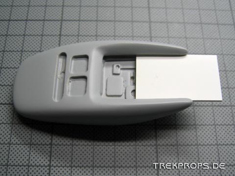
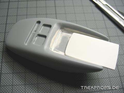
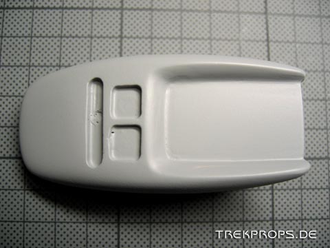
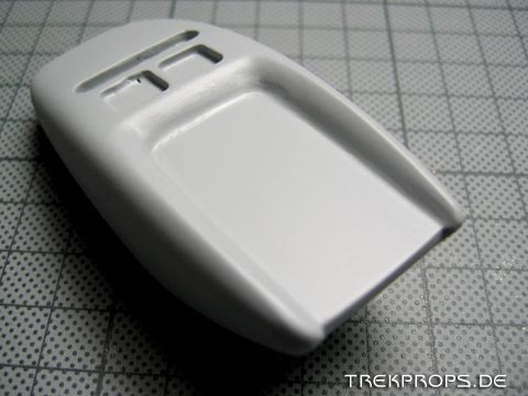
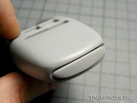
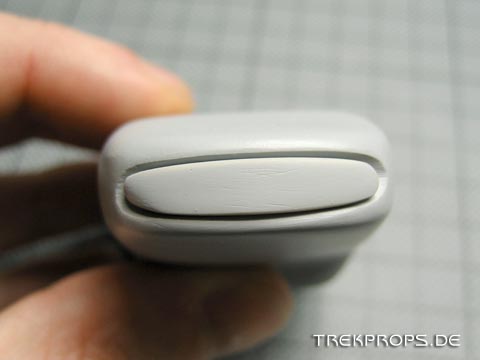
As a special feature, this kit allowed you to take a look inside the phaser. To implement this into the finished replica, the builder is supposed to cut a piece of styrene to fit as a thumbpad which then could be slid out to reveal the “circuits”.
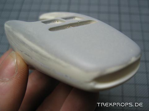
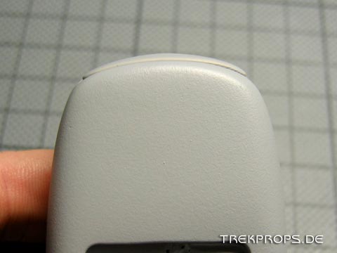
Note the two struts at the rear end of the body. They are caused by the resin being poured into the mold and also getting into the air vents that probably had been created to allow the air to escape as the resin was poured. They of course need to be sanded off.
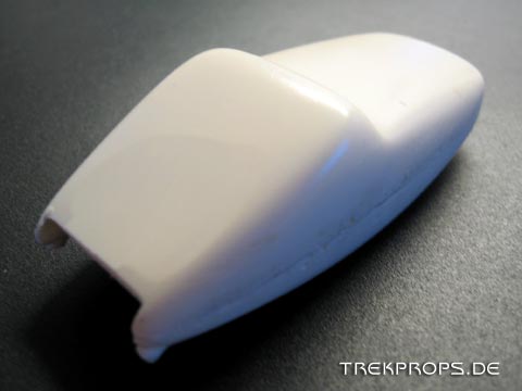
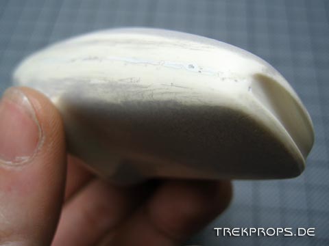
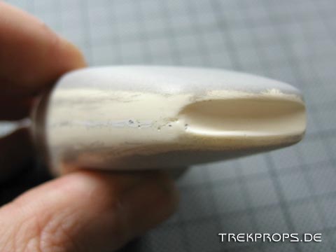
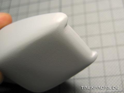
Another thing you can see in this picture very well is that the sides of the casting were pretty raw. This was probably caused by the seam line running here, which is inevitable with all two part silicone molds.
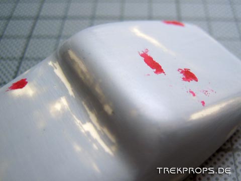
This is after the first filling work was done. I filled the defects on the sides using polyester putty and sanded it down. Also the first splash-coat is already applied here. It revealed where I had to do more repair work.
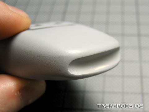
As you can see, the muzzle of the phaser was originally solid and supposed to be implemented using paint only. However, I had other plans for it. More on that later though…
I then filled small holes and imperfections using spot putty. Don’t apply too much of it unless you want to make the sanding process any more difficult than it has to be.
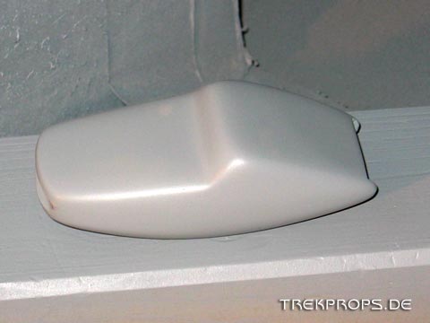
The phaser during priming. Several thin coats are in order to prevent paint running down the body.
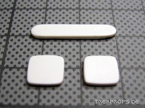
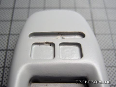
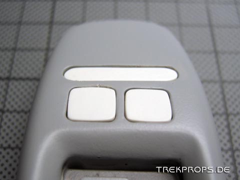
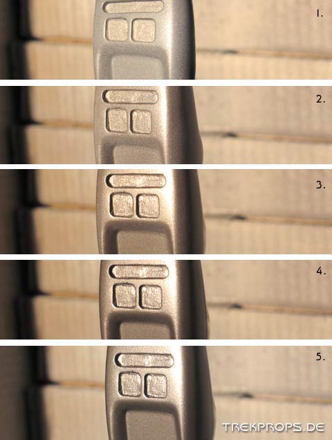
Here you can see the controls. They are nothing more than styrene cut and sanded to shape to fit into the respective recesses on the body.
Fits like a glove!
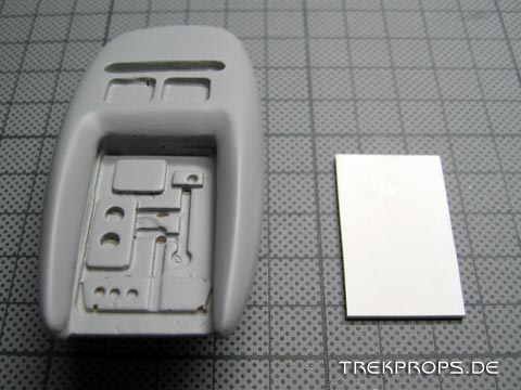
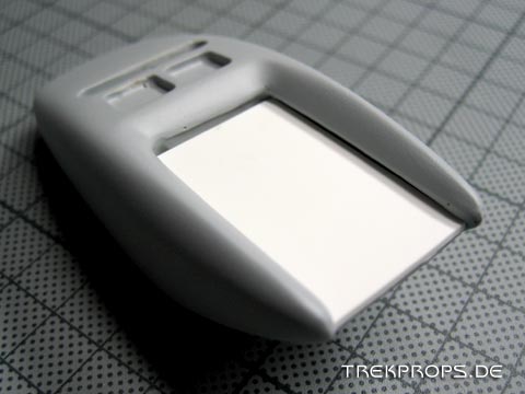
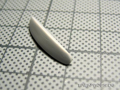
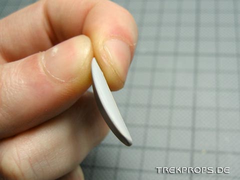
Next up was the cover for the “inner workings” of the phaser. After I had cut a piece of styrene to fit the designated area, I realized that it didn’t fill all the gaps present. Also, there was no way to make it fit in perfectly and keep the functionality of sliding it out.
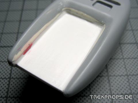
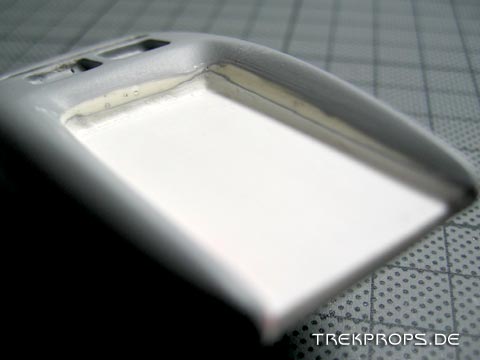
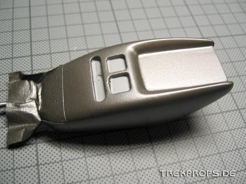
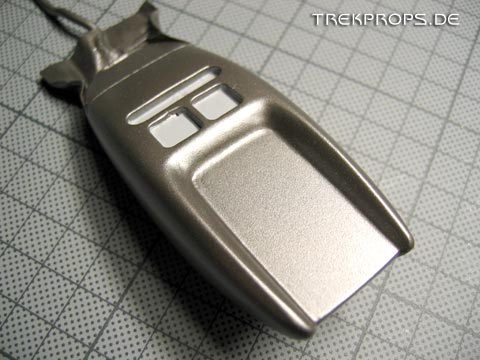
Because of this, and because there was never seen a open “cricket” phaser in TNG or elsewhere, I decided to seal the thumb pad using putty and to make a solid prop out of it:
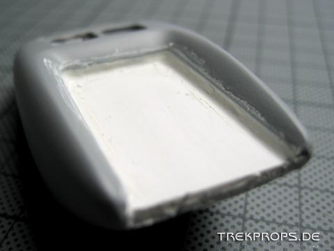
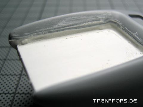
Sanding all of these edges and corners smooth was a challenge, especially because the corners were supposed to keep their curvatures.
Here’s the result of several puttying and sanding passes. The remodeling of this area was extremely elaborate and required a lot of patience.
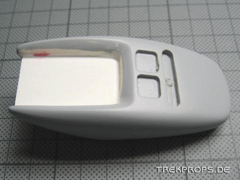
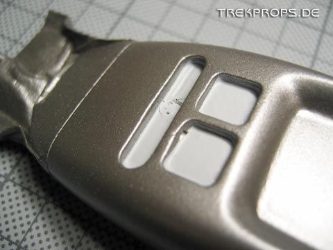
After I had applied a coat of primer here , I realized that the area of the thumb pad was too small and also that the recess of the cover was too deep. So, I repeated the last step and cut another piece of styrene to fit. Then I once again had to use putty to seal all the gaps.
Here’s the final result after the last coat of primer:
The rear end required some effort, too. I had to join the pieces of styrene with the resin body to make it look smooth and “natural”.
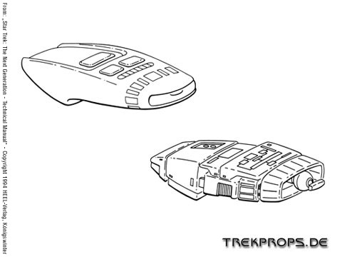
Now back to the muzzle: As I said, I had a special plan for that. Instead of simply painting it red, I wanted to insert a seperate piece as an emitter. I thought that would look more authentic and I also used this picture from “Star Trek: The Next Generation – Technical Manual” as a reference:
So, I took a small round file and removed some material from the front of the phaser until I thought it looked right:
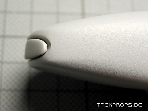
Next I shaped the muzzle insert from a spare piece of resin. It nicely re-completed the forward shape of the phaser and fitted inside the opening very well. Since we’re talking about very small sizes here, the task of modeling the muzzle was not an easy one. My own fingers often were in the way holding the piece of resin.
It would have been nice to do the muzzle piece from a translucent red material, but I decided not to pursue this because the muzzle should have the same appearance as the particle vents on the pre-fire chamber. Since there was no way to do them transparent on this build, I chose to do the muzzle piece opaque as well.
Here’s the emitter being test fitted into the phaser body:
Now all of the seperate pieces were finished and I could move along to painting them!
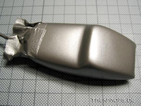
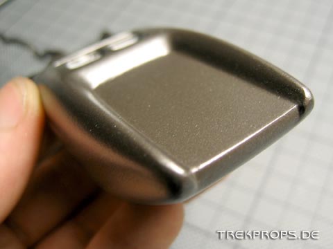
First I painted the phaser body using the standard color for Starfleet equipment: Plasti-kote 7173. This paint is of course not available in its original form in Germany and that’s why I went to a spray paint specialist and got me the accurate color custom mixed using a color sample of the original paint.
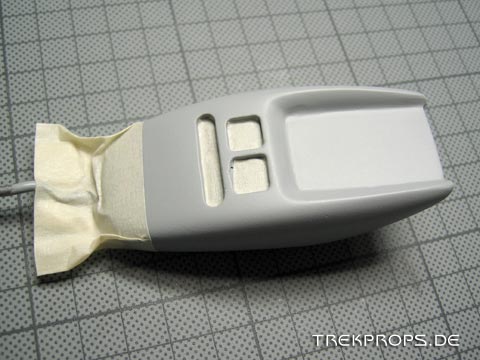
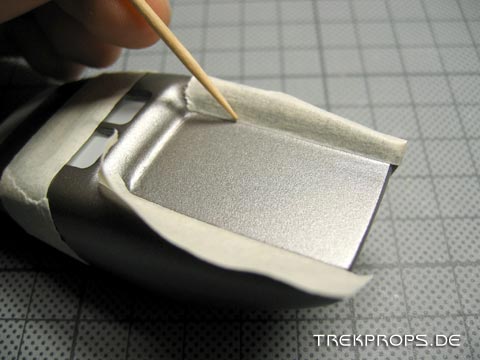
All of the areas that are not supposed to come in contact with the paint have to be masked off before spraying. In this case I masked the recesses of the controls so that the coats of paint won’t make them smaller to make sure my buttons would still fit in there later.
Just with the primer it’s extremely important to spray several thin coats instead of one thick layer of paint. It’s alright if the primer is still visible after the first coat! With the subsequent coats the paint then becomes more and more dominant until the surface is perfectly covered. Between coats you should wait 5 to 10 minutes to let them dry.
Try this trick to avoid ugly paint blobs: Place the can into warm water for a few minutes to heaten up the paint. It then disperses a lot finer.
Here’s the result:
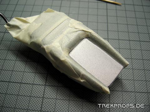
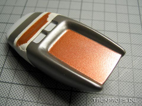
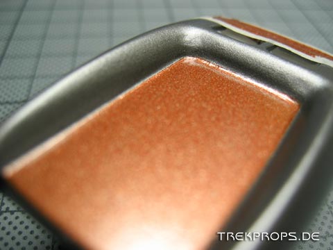
The second color was next: Bronze. Again, I masked all the areas except the thumb pad. To help attach the masking tape I sometimes use toothpicks in tricky situations. It’s important to stick the tape very tight onto the surface to prevent paint from getting under it which would make the paint line look messy.
Everything but the thumb pad had been masked off:
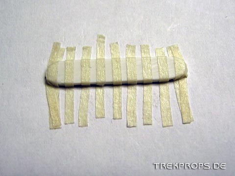
The power bar was also ready to be painted now. This piece of styrene is merely 25 millimetres long and the strips of masking tape were 1 millimetre thick. Masking this tiny thing required some patience.
If I were to do this today, I’d probably use a printed graphic instead of painting styrene…
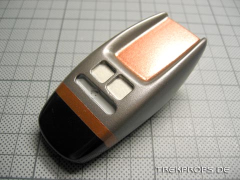
This is the phaser after the second color had been applied and the tape had been removed:
Very nice!
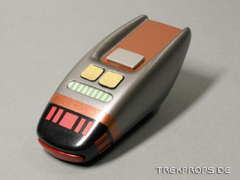
These are all the finished greeblies: Muzzle emitter, power bar, control buttons and the trigger. I glued golden paper onto the styrene control buttons to make them neither too glossy nor too dull. Then I used a black marker to paint the sides. The trigger is also styrene painted silver.
Several masking and painting passes later the forward part and the muzzle of the phaser were finished. It still looked quite unfinished though.
Next the greeblies had to be attached. The emitter had to be inserted into the muzzle, the power bar and the control buttons had to be glued into the appropriate indentations and the trigger had to be attached to the thumb pad. To provide the glue with a better grip to bite on, I carefully roughened up the respective surfaces using sandpaper.
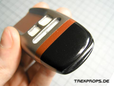
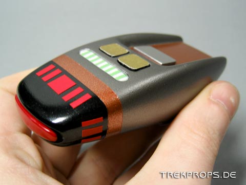
Now only one other thing was missing: The particle vents on the prefire chamber. A lot of replicas show them to be angular. However, the originals always had straight vents. To make my phaser as accurate as possible, I of course decided to make them straight as well. On the top and bottom side, there are one large and four small vents each. On each side there are three of them. Originally I wanted to put them on using red paint. It then however became clear that red vinyl tape was the better solution for this. It is less error-prone and also looked better.
And here is the finished phaser:
Although there are some things that I could have done better in this build, I’m still very satisfied with it.



One Response to “Buildup: Type I “Cricket” Phaser”
Ken on: May 18th, 2012 at 00:05
I’ve been trying to eBay the Cricket Phaser keychain, got about 3 days to go. In the interim, I’m trying to make Sculpey Cricket Phaser variants by hand, just for fun. Your pics might help me get a more authentic look for a standard phaser. I loved the First Contact cricket phaser trigger/setting bar version I saw, and that’s the kind I usually make, using white duct tape and clear tape for protection, until I can get printable sticker paper. GREAT pics, BTW.
Post a Comment
Want to see your picture next to your comment? Go get a Gravatar!